Dithered Rendering
Creating stylised 3D graphics using dithering in Unity's Universal Render Pipeline
Summary
An easy way of improving the visuals of your PSX-style game is to squash down the resolution and use dithering to reduce the number of colours while preserving the shading and depth. This tutorial goes over the basics of rendering using dithering, particularly to achieve this psx style. (as well as how to use shadergraph and a custom render feature in unity’s URP)
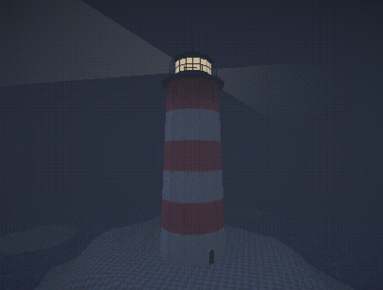
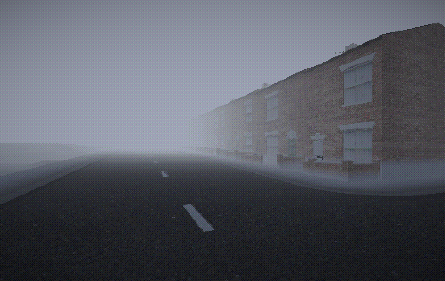
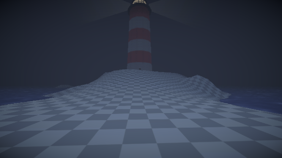
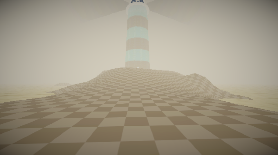
these are two scenes from a very work in progress game, currently called Twin Angels
Dithered Rendering in URP
Intro
Some time in early 2022 I got really into visual shaders for games, particularly Return of the Obra Dinn’s one-bit dithering technique, and tried recreating it for some smaller projects.
Flash forward to a few years later and I’ve continued to work on this dithering shader and found it really cool, particularly for a PSX style game. Most of what this post covers can be applied in a variety of different ways depending on what you specifically want to do, and can even be adapted for use as a surface shader.
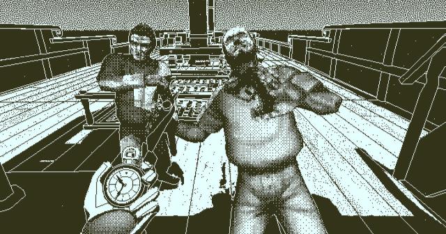
if you’re interested in learning more about how Obra Dinn achieves its visuals here’s a really useful resource
The Basics
Before we dig into things its probably helpful to have at least a basic understanding of Unity’s Universal Render Pipeline and Shadergraph, particularly the latter as you’ll need to understand how to make a graph and the basics behind creating and connecting nodes (there are plenty of youtube tutorials on the subject if you’re uninitiated).
Dithering
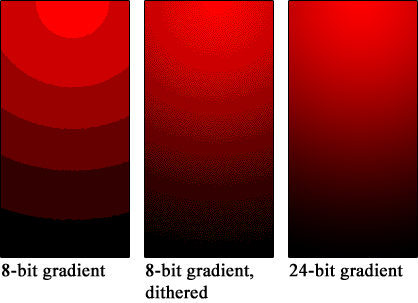
Dithering is an old process of smoothly transitioning between two values in an image, essentially ‘faking’ more data than really exists. Its primary function was to avoid colour banding in compressed images (the ugly big flat surfaces of colour in low-quality pictures) by faking a smooth gradient using clusters of noisy pixels.
It’s a pretty simple effect, but by chequerboarding pixels of two different colours together, at a distance they blend into one mid-point colour. Using this, all you do is reduce or increase the density of this chequerboard pattern depending on how far between the two colours a point is.
Using the Bayer Matrix dithering texture we can easily dither between two values. Using this ‘edge’ value sliding up and down in the example we can see which pixels in the matrix are darker than this value, which will be black, and which are lighter, which will be white. In graphics programming this is called a step(edge, value) function, which takes an edge and a value, returning 1 if the value is greater than the edge, and 0 if the value is lower.
We can use the result of this (the little dither square on the right) to interpolate between two values. The easiest example of this is a one-bit shader that interpolates between a background colour and a highlight colour depending on the brightness of each pixel. The basic idea is that this dithering texture is tiled across the entire screen, and then for every pixel in the rendered image we check if the luminocity is above or below that same pixel in the tiled bayer matrix texture, returning either black or white.
The luminosity of a pixel
pis calculated in a few different ways depending on your specific purpose, but I went with(0.2126 * p.r) + (0.7152 * p.g) + (0.0722 * p.b)cheeky little tip for ya
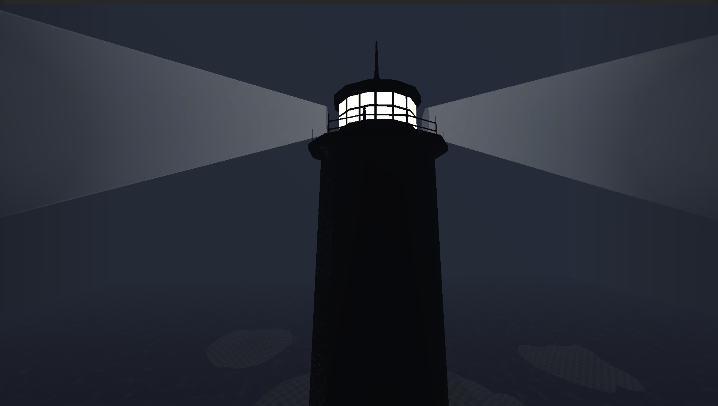
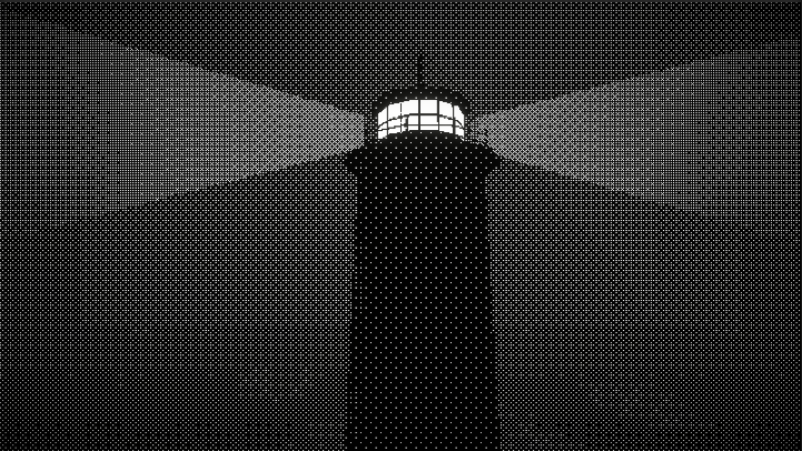
Here I have a shot of the lighthouse rendered normally, no dithering, against one rendered using a one-bit dithering filter:
(these can look weird on some screens, click to enhance the one-bit picture to see it better)
This effect has been popularised by games like World of Horror and Who’s Lila (one of my favourite games ever by the way), although both these games also include hand-drawn assets or additional details like edge-detection to enhance the visual appeal of the shader.
now that you get the basics behind dithering we can move onto the render feature.
Custom Render Feature
In URP in order to add our own shader to the render pipeline we need to create a custom render feature (fun I know). You can refer to the github1 files to see the basic structure for a custom render pass and custom render feature, which I will briefly explain here.
Watch Out: this stuff is super complicated and I barely understand it, but what I have works
I’m definitely not an expert in URP or render features, but I do understand the basics of it. Our custom little render thingamabob comes in two major parts:
- the render pass
- the render feature
You can skip right to setting things up if you don’t care about what these two scripts actually do, but I think its interesting.
Render Pass
The render pass is the little bit of code handled by URP that tells it how to use our material to render the game. For our purposes (squashing the resolution down and then applying our custom filter) this is done in two Blit2 passes:
- the first renders the screen to a render texture, squashing the screen down to our desired resolution.
- the second renders from that render texture to the screen again, passing it through our custom material, and adding the dithering effect.
The DitherPass class inherits from ScriptableRenderPass, and we’ll use the override function OnCameraSetup(CommandBuffer cmd, ref RenderingData renderingData) to retrieve the RenderTargetIdentifier for the colorBuffer, which is the identifier for the render texture that the game will display on the players screen, and is what the scene is originally rendered to, and then use the override function Execute(ScriptableRenderContext context, ref RenderingData renderingData) to add our two blits, one from the colorBuffer to our pixelBuffer (the custom render texture with our squashed down size, that we will give to the render pass using our render feature), and the other from our pixelBuffer BACK to our colourBuffer, passing it through the dithering material which we will make in a moment.
If that was a little confusing it can be summarised as
- Screen drawn to the colorBuffer by the game
- colorBuffer copied across and squashed down into our custom render texture (the pixel buffer)
- this squashed down image is then redrawn to the screen using our material, which applies the dithering filter
remember all these files are accessible on the github1
1
2
3
4
5
6
7
8
9
10
11
12
13
14
15
16
17
18
19
20
21
22
23
24
25
26
27
28
29
30
31
32
33
34
35
36
37
38
39
40
41
using UnityEngine.Rendering;
using UnityEngine.Rendering.Universal;

public class DitherPass : ScriptableRenderPass
{
    // the settings made in the RenderFeature
    private DitherPassFeature.DitherSettings settings;

    // the two render textures that will be written to and from
    private RenderTargetIdentifier colorBuffer, pixelBuffer;

    // construct the render
    public DitherPass(DitherPassFeature.DitherSettings settings)
    {
        this.settings = settings;
        renderPassEvent = settings.renderPassEvent;

        pixelBuffer = settings.renderTex;
    }

    // retrieve the colorBuffer
    public override void OnCameraSetup(CommandBuffer cmd, ref RenderingData renderingData)
    {
        colorBuffer = renderingData.cameraData.renderer.cameraColorTargetHandle;
    }

    // execute the two blits and apply the material
    public override void Execute(ScriptableRenderContext context, ref RenderingData renderingData)
    {
        // get a command buffer
        CommandBuffer cmd = CommandBufferPool.Get();

        // queue render from colour buffer to our pixel buffer
        cmd.Blit(colorBuffer, pixelBuffer);
        // queue render back from the pixel buffer to the screen, using our material
        cmd.Blit(pixelBuffer, colorBuffer, settings.ditherMaterial);

        context.ExecuteCommandBuffer(cmd);
        CommandBufferPool.Release(cmd);
    }
}
Render Feature
The render feature is the part of the code that sets up our render pass, and handles actually adding the render pass to the pipeline, and the settings for the render pass.
The DitherRenderFeature class inherets from ScriptableRenderFeature which lets us override two important functions: Create() and AddRenderPasses(ScriptableRenderer renderer, ref RenderingData renderingData).
We will use a struct called DitherSettings to hold all of the settings and necessary data for our render, including the RenderPassEvent, which tells the pipeline what stage this render occurs (e.g. after rendering transparent objects, before post processing, etc.), the material we will assign our shadergraph shader to, and the RenderTexture in the project files that has your desired resolution. This struct will be serialized in the inspector, and can be seen in inspector for your URP render asset once its added.
In the Create() function we’ll create our DitherPass using its constructor, and passing it our settings, as well as setting the renderPassEvent to the one in the settings.
once again you can find these files on the github1
1
2
3
4
5
6
7
8
9
10
11
12
13
14
15
16
17
18
19
20
21
22
23
24
25
26
27
28
29
30
31
32
33
34
35
36
37
38
39
using UnityEngine;
using UnityEngine.Rendering.Universal;

public class DitherPassFeature : ScriptableRendererFeature
{
    // the settings for our render pass that will be passed in the constructor
    [System.Serializable]
    public struct DitherSettings
    {
        // when during the rendering process this pass will happen
        public RenderPassEvent renderPassEvent;
        // the material that the render will use
        public Material ditherMaterial;
        // the render texture of our squashed-down resolution
        public RenderTexture renderTex;
    }

    private DitherPass ditherPass;
    public DitherSettings ditherSettings;

    // creating the render pass
    public override void Create()
    {
        ditherPass = new DitherPass(ditherSettings);

        ditherPass.renderPassEvent = ditherSettings.renderPassEvent;
    }

    // adding the render pass to the renderer
    public override void AddRenderPasses(ScriptableRenderer renderer, ref RenderingData renderingData)
    {
        // only adding it if the material AND render texture are set up, so that there are no errors
        if (ditherSettings.ditherMaterial != null && ditherSettings.renderTex != null)
        {
            // adding our pass to the render pipeline
            renderer.EnqueuePass(ditherPass);
        }
    }
}
making custom render passes is how you do any custom post processing in URP, so its useful information even if you don’t intend to use dithering in every project
Basic Setup
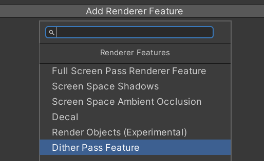
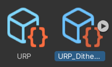 Once you have these two scripts in your project, and hopefully have set up URP so that you have a Universal Render Pipeline Asset and Unviersal Renderer Data objects, you can add your render pass to the Universal Renderer Data object.
By clicking ‘Add Render Feature’ and selecting your custom render feature from the dropdown, you’ve added it to your render pipeline. Hooray! but unfortunately you haven’t actually set anything else up yet, so either nothing has happened or your project has started throwing errors.
The next thing to do is to create a Render Texture asset to assign to this render feature in the inspector, as well as set up your Render Pass Event (which should probably be before rendering post processing).
You can create a Render Texture by doing Assets > Create > Custom Render Texture. Since this will be the squashed down resolution we want, its probably good to set it to something like 640 x 360, or 480 x 270, basically some multiple of 16 x 9 (the standard screen ratio). If you want to try some different ratios, like 4x3 for that retro aesthetic, thats probably better done by adding black bars either side of the screen than by actually messing with the output resolution, since on a full-screen application it will warp and stretch otherwise. Its very important that you make sure your Render Texture has no anti-aliasing and Filter Mode is set to Point, since if either of these things aren’t true it will look strange.
Warning: if you want your application to be resizable, or in a resolution smaller than 640 x 360, you’ll notice some visual disturbances. Hopefully you’re smarter than me and can fix those, since I’ve chosen to live with them. God save us all
Second Warning: For some arcane reason, setting your Render Pass Event to ‘after post processing’ makes the whole thing not work. Sorry about that
now you hopefully have a working render feature! In the next little section we’ll make a test shader using Shadergraph to make sure its all working good.
The Shader
Although we probably could write the shader out in HLSL, its more fun to play around with using unity’s Shadergraph, since it helps to visualise the shader as it progresses through each node.
The basic idea behind our dithering shader is 4 steps:
- Round all the colours down to the nearest multiple of our ColourDepth (higher ColourDepth means fewer colours, ironically).
- Get the remainder of this division, which serves as how far along the gradient between the current and next multiple of ColourDepth is.
- Apply the dithering texture to this remainder, using it to smoothly interpolate between each step of the ColourDepth multiples.
- add this back to the result from step 1.
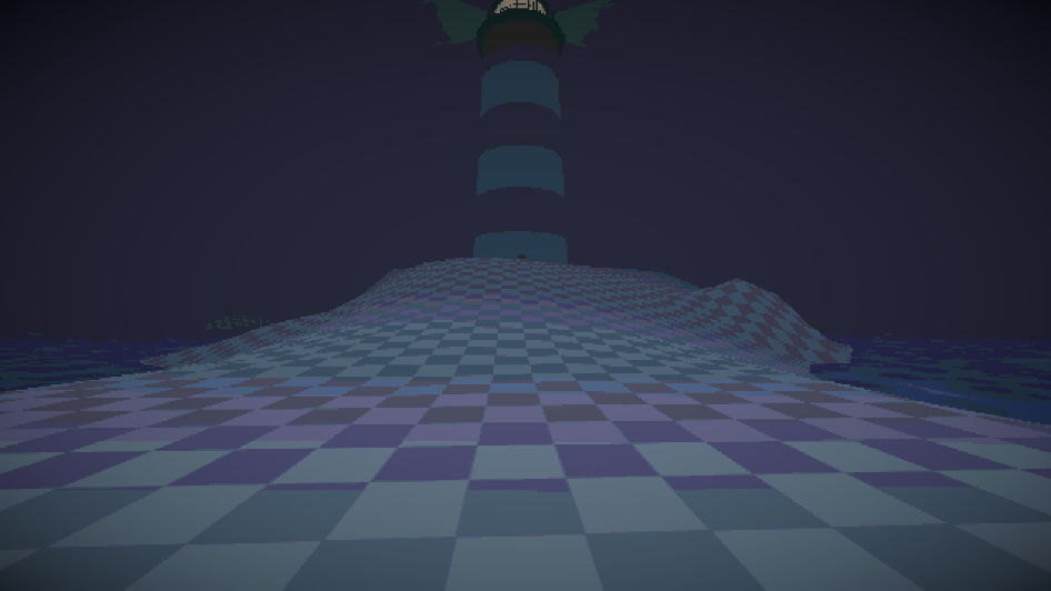
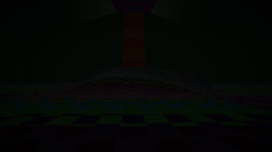
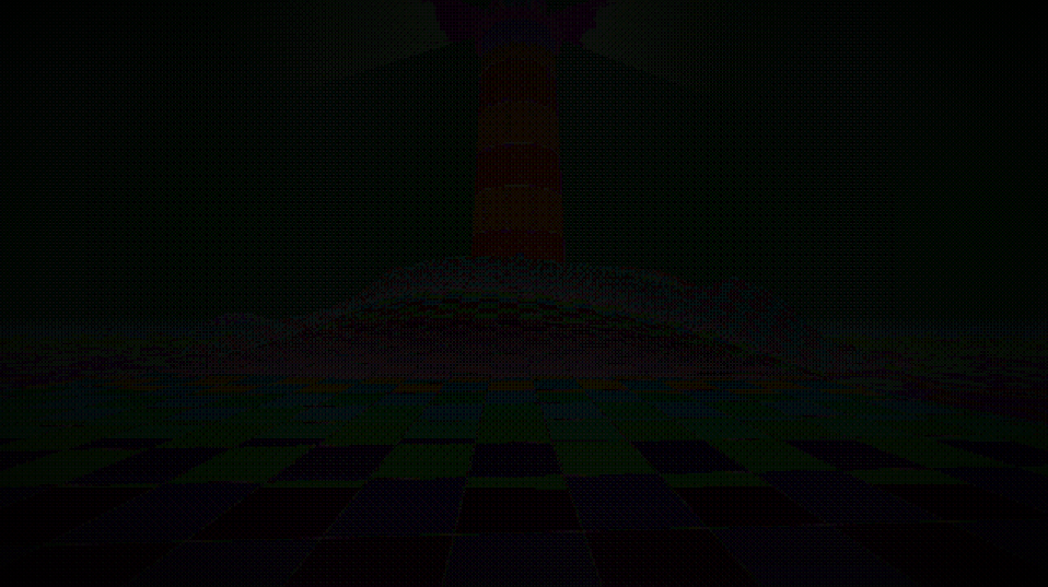
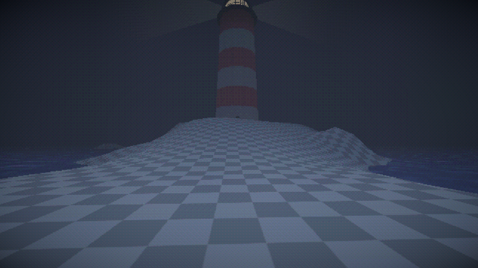
Here’s the lighthouse scene again, this time showcasing each step of our shader, first without any effects applied. As you can see, the second and third stages are really dark, this is because we’re using tiny number values, which are visually represented as very very dark colours. Games like Buckshot Roulette just use the result of the first step, creating cool colour banding (callback to how dithering was originally used to alleviate colour banding in compressed images)
Shadergraph Setup
Shadergraph is unity’s node-based shader editor. If you have installed and set up URP, you should be able to make a Fullscreen Shader Graph by doing Assets > Create > Shader Graph > URP > Fullscreen Shader Graph.
In order to make this shader work with our custom render pass, we need to first give it a Texture2D parameter called MainTex. This name is really important, as the reference name for this variable, _MainTex, needs to be accurate in order for the render pipeline to give our material the correct information. 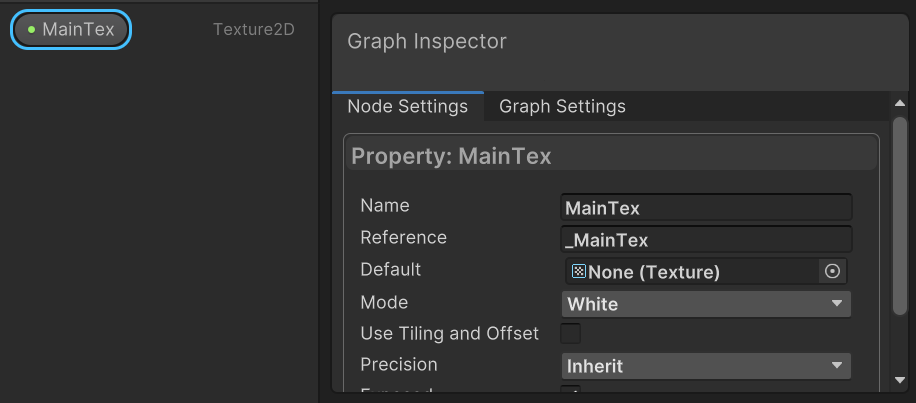
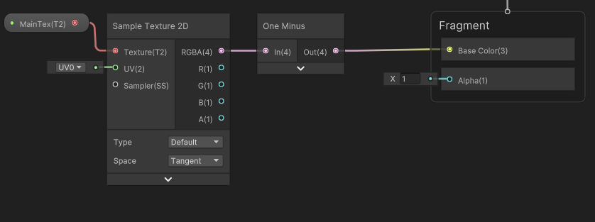
This MainTex parameter is the texture for our render, and contains the result of the screen’s render. To create a simple test shader, just put this node into a One-Minus node, and then have that output to the base colour out value.
Then, you can make a material using Assets > Create > Material and drag the Shadergraph asset onto that material. You can then assign this material in the render feature settings on your URP asset, which should hopefully output this inverted colours render. (without, and then with the shader active)
Constructing The Shader
For our shader to work we need to setup several parameters. Firstly, as mentioned before, a MainTex texture2D parameter, but also a DitherTex texture2D. We will have to assign this texture in the inspector for our material, and we’ll assign the mayer dither matrix image.
In addition to these two textures, we need a ColourDepth float, which determines how heavy the colour rounding will be, and a ColourClamp float, which cuts off the very top and bottom of the dither texture, making it flatten out faster. I wouldn’t recommend setting the ColourClamp to anything higher than .1, and setting it to anything higher than .5 breaks it all.
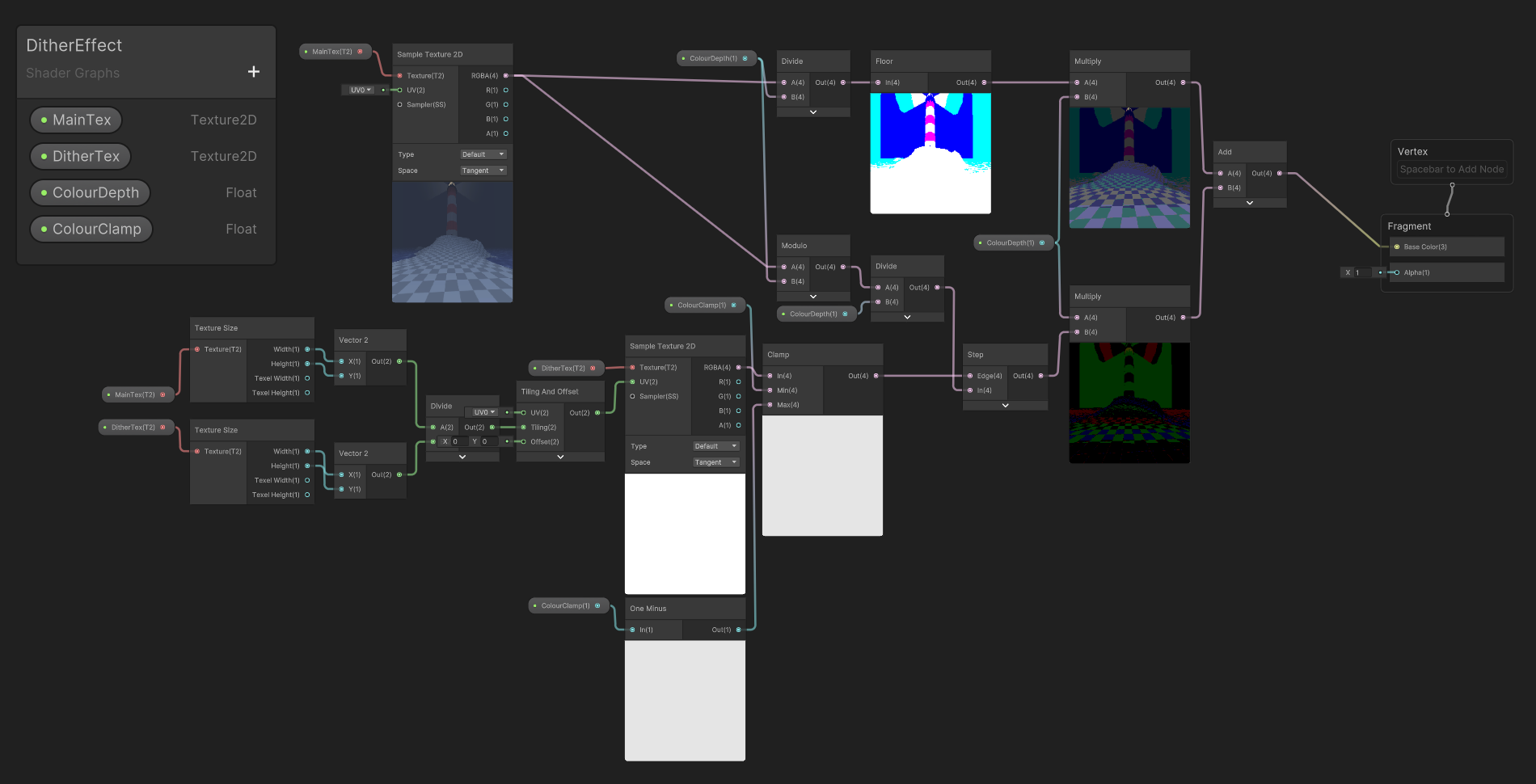
Here’s the graph in its entirety, but I will break down each part of it in a moment.
lets start with the dithering texture itself
Working With The Dither Texture
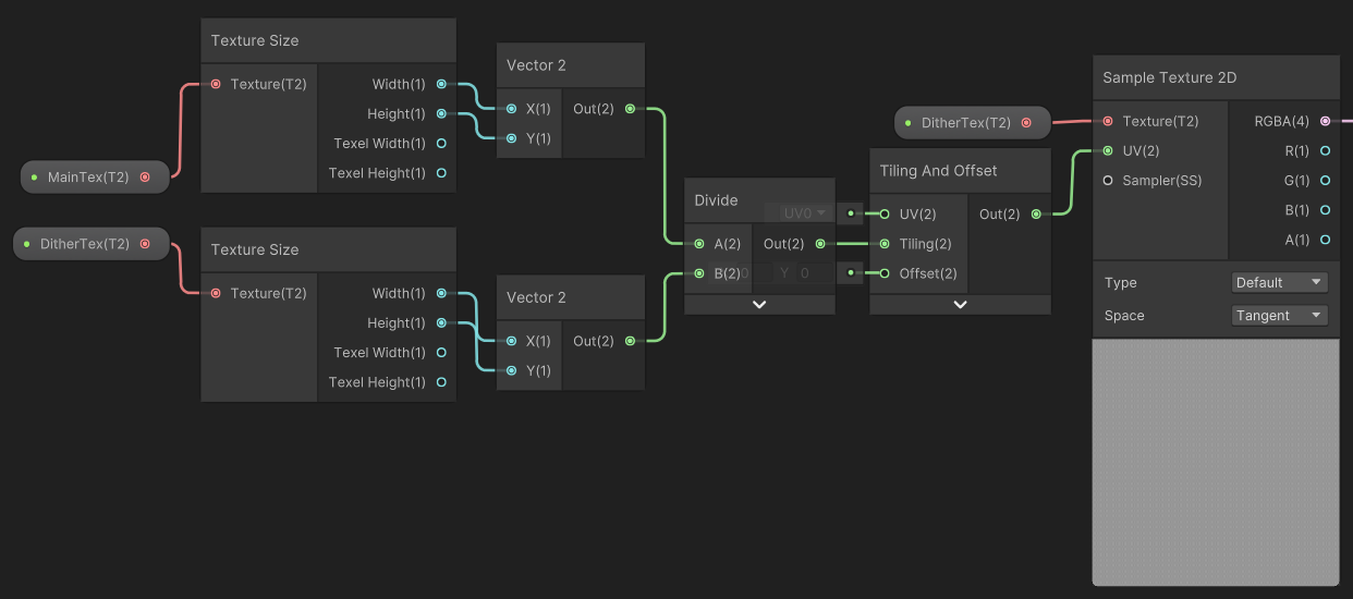
This little bit of the graph works by dividing the size of the MainTex texture (and therefore the size of the screen) by the size of the DitherTex texture. Using this value as the tiling input in a Tiling and Offset node, we effectively repeat this image across the entire screen. This will be really useful when we need to use it to interpolate between stages of the rounded colours.
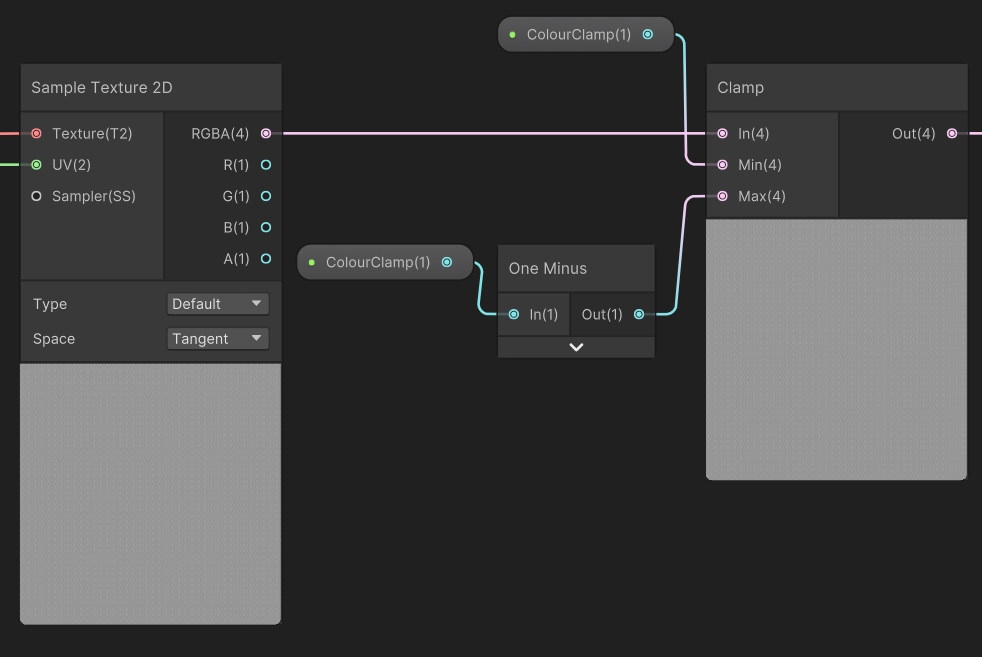
after this, we use the ColourClamp variable to clamp the upper and lower limits of the dither texture, making it flatten out quicker.
now we can move onto handling the colours
Colour Magic
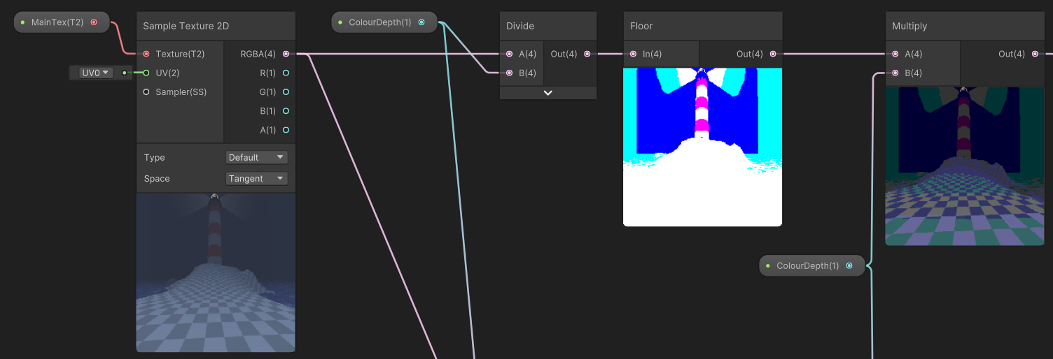
First, we round the colour of the pixel down to the nearest multiple of ColourDepth. The equation to round a value down to the nearest variable is floor(value / multiple) * multple, which we do to the sampled RGBA value from the Sample Texture 2D node.
also, if you replace
floorin that equation withround, you’ll round to the nearest multiple, andceilto round up to the nearest multiple. Don’t do that for this though, rounding down is important
In our shadergraph, that equation looks like this:
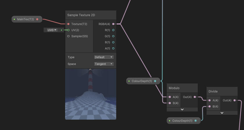
Ignore all the lines disappearing off the bottom of the screen, thats for stage 2.
Now that we have the rounded colours, we need the remainder of this division, which we can calculate using a modulo node. In order to sample our dither matrix, we need a value between 0 and 1 that represents the percentage of the way through the gradient each point is, which is calculated using value / maxvalue = percent. In our shadergraph, this means dividing the result of our modulo operation by the ColourDepth parameter.
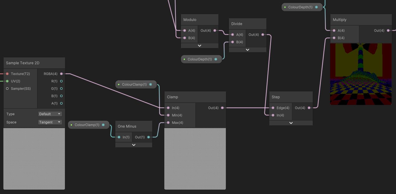
Now that we have our percentage, we can run the result though the step node, and then multiply the result by the colour steps, which is our parameter ColourDepth.
Now all thats left is to add this final result to the result of our colour rounding, and we have a finished graph.
You can now happily enjoy the many fruits of your labour. I hope you make some cool scenes using this shader, and learned how to create a custom post processing path in unity!!
